Device Type: Optical or Mechanical Encoders
High-resolution Quadrature devices usually consist of a pair of optical sensors and an encoder wheel. Examples of such devices are:
- 12-way rotary switches such as the Happ Controls Rotary Joystick. See App Note AN1001
 |
 |
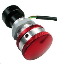 |
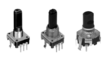
| ALPS EC12 Mechanical |
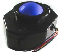
Ultimarc U-Trak |
Ultimarc SpinTrak |
Quadrature devices can be used in two ways. They can be used to control the mouse pointer in an X, Y or Z direction, or they can be used to repeatedly pulse gamepad buttons. In general, mouse mode is used for high-resolution optical encoders and button mode for low-res mechanical but there may be applications where the opposite mode is useful.
Quadrature devices use two input pins per device, and optical devices will require GND and 5V pins. Mechanical encoders require GND only, and this is the center pin on 3-pin devices.
Windows allows one instance of each axis when defined as Mouse (ie X, Y, Z) but if you are using multiple U-HID boards, Windows can recognise each board as a different mouse, using DirectInput.
Devices should be capable of operating with a 5 volt supply (not required for mechanical encoders).
This can be obtained either by configuring a pin as 5V or using one of the fixed 5V sources on connector J7
They also require ground, which can be connected to a configured pin or one of the ground pins on each modular connector.
Note that only certain pins can be configured for quadrature devices. These can be seen in U-Config by clicking on the "Quadrature" line in the PCB image. Appropriate pins will be highlighted. Two pins are used per device. An X-Y device such as a trackball counts as two devices and therefore uses 4 pins.
Mouse Mode
Encoders configured in this more simply move the mouse pointer in the X, Y or Z direction. Note the Z axis in Windows performs differently to X and Y. It accepts a fixed displacement per data packet rather than a variable one. This means the Z axis might not be suitable for many applications as it is very sensitive when using a high-res encoder.
Button Pulse Mode.
In this mode, the quadrature device is assigned to a pair of Game Controller buttons. The pairs are buttons 1,2, buttons 3,4 etc up to 15,16.
When the encoder is turned in one direction, the first button will be repeatedly "pressed". When turned in the other direction, the other button of the pair will be repeatedly "pressed".
The press time is configurable. This is a global setting on the "Calibration" page of U-Config. The setting here can be set from 2 to 32. The figure is actually the number of USB data packets sent for each press. Between each press, there must of course be a "release" period and this is the same time as the press.
It might be necessary to experiment with this setting as there is a trade-off. Too fast a setting will cause presses to be missed by the application, and too slow will cause slow response of the control.
When this mode is used for high-resolution encoders, the buttons will be pulsed at the maximum configured speed which is much higher than the real pulse-rate from the encoder. |